Assembly Guide
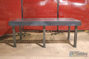
BPT Model L · 2400 × 1200 × 150mm · 6mm S275 Structural Steel
Before You Start
What's in the box
| Qty | Component | Description |
|---|---|---|
| 1 | Top plate | 2400 × 1200 × 6mm S275, full hole grid |
| 2 | Long sidewalls | 2400 × 150 × 6mm, hole grid both faces |
| 2 | Short end walls | 1200 × 150 × 6mm, hole grid both faces |
| 3 | Brace A | 2400 × 150 × 6mm torsion-ribs |
| 2 | Brace AA | 2400 × 150 × 6mm torsion-ribs |
| 6 | Brace B | 1200 × 150 × 6mm Cross-length torsion ribs |
| 4 | Brace BB | 1200 × 150 × 6mm Cross-length torsion ribs |
| 1 | Brace BBB | 1200 × 150 × 6mm Cross-length torsion ribs |
| 6 | Legs | 70 × 70 × 3mm RHS, cut to ordered height |
| 4 | Corner leg plates | 6mm plate |
| 2 | Middle leg plates | 6mm plate |
| 6 | Leg mount plates | 6mm plate, pre-cut, weld to legs |
| 6 | Leg base plates | 6mm plate, pre-cut, weld to legs |
| 24 | Leg Fixing sets | M16 x 40mm - grade 8.8 bolts, nuts & washers |
Tools required
- MIG or TIG welder — for final assembly
- 17mm spanner / socket set — M10 hardware
- 24mm spanner / socket set — M16 hardware
- Tape measure — diagonal measurement for squaring
- Rubber mallet — seating tab & slot joints
- Spirit level — levelling finished table
- PPE — welding mask, gloves, steel toe boots
- M10 threaded rod, nuts & washers — grade 8.8, qty lots! - Used inconjunction with the Assembly brackets
- BPT assembly brackets — for clamping in tension, qty 25
💡 A second pair of hands is helpful for Step 3 (lid placement) but not essential.
Step-by-Step Assembly

Unpack and inspect all components
Lay all panels flat on a clean workshop floor. Check every component against the BOM in Section 01. Inspect edges for any transit damage — minor surface marks on raw steel are normal and do not affect structural integrity.
Panels are laser-cut and will have slight burring on cut edges. Wear gloves when handling bare panels. Keep the top plate face-down and protected until it is needed in Step 2.
Lay the top plate face-down and build the rib lattice on top
Place the top plate face-down on a flat, clean surface — either on a pallet or steels, just something to raise the plate in the fourcorners with the centre supported, so that you are able to safely access the underside when clamping . The underside of the top plate becomes your assembly datum: everything builds up from it.
Begin slotting the internal ribs together to form the lattice grid directly on top of the plate. Long ribs (cross-length) and short ribs (cross-width) interlock at their half-depth slots — work from the centre outward. The ribs should sit flush against the plate with no gaps.
- Top plate face-down, surface protected
- All long ribs slotted together
- All short ribs interlocked into lattice
- Lattice sitting flat and flush against plate — no rocking
Fit the four sidewalls
With the rib lattice in place on the top plate, slide the two long sidewalls (2400mm) into position along each long edge. The sidewall tabs locate into the corresponding slots on the outermost ribs. Follow with the two short end walls (1200mm) at each end.
Use a rubber mallet to fully seat each tab into its slot — panels should locate positively with no play. Do not force panels that feel misaligned; check the rib orientation first.
- Both long sidewalls seated and tabbed
- Both short end walls seated and tabbed
- No gaps between sidewall bottom edge and top plate
- Assembly self-supporting — no lean or twist
Clamp the assembly using threaded rod and assembly brackets
Thread the threaded rods (m10) through the pre-cut holes in the sidewalls, passing through the rib lattice. Fit the assembly brackets over the intersecting lattice ribs, and use penny washers at the other end though the table surface. — these bear against the outer face of the sidewalls and distribute clamping load evenly across the panel.
Run nuts up finger-tight on all rods first. Then tighten progressively, working from the centre of each wall outward, clamping in all directions simultaneously. This draws the sidewalls tight against the rib edges and presses the entire lattice firmly against the top plate.
- All threaded rods installed and located
- Assembly brackets fitted at all rod ends
- Nuts finger-tight on all rods before final tensioning
- Clamped progressively centre-out, all directions
- No gaps visible between any panels
Check square, then final tighten
Before final tightening, measure corner-to-corner diagonals across the top plate. Both diagonals must match within 2mm. If the assembly is out of square, slacken the rods slightly and apply gentle racking pressure to the longer diagonal corner, then re-tighten.
Once square, bring all rods to final tension in even passes. The assembly is now fully clamped and rigid.
- Diagonal measurements equal within 2mm
- All rods at final even tension
- No panel movement or flex
- Assembly fully rigid in all axes
Weld the legs, panels and flip upright
The table is still upside-down with the top plate face-down. This is the correct position to start welding. Position each leg mount plate over its corresponding pre-drilled location on the underside of the torsion box. Clamp each leg square using an engineer's square before tacking.
Check all legs are vertical and at equal height before committing to full welds. Once tacked and confirmed, run full fillet welds on all four sides of each leg-to-plate junction. Begin to start welding all the internal faces, remember to distribute the heat as this can cause distortion issues. Allow to fully cool before flipping.
- All 6 legs clamped and tacked square
- Leg heights equal — measure from datum plate
- Full fillet welds, all 4 sides of each leg
- Welds fully cool before flipping upright
Flip upright and level
Once welds are fully cool, flip the table upright onto its legs. Place a spirit level on the top surface and check both axes. The table should sit level to within 1mm across the full 2400mm span.
If adjustment is needed, shim low legs with steel plate shims (not supplied). Do not attempt to level by bending legs — this will stress the welds. Once level, wipe the surface with a light oil to protect the raw steel finish.
- Table upright, all 6 legs on floor
- Spirit level within 1mm across 2400mm
- No rocking under applied corner load
- Surface wiped with light oil
Fixings Specification
Fixings are supplied with the kit — source extras from any fastener supplier (Accu, Fastenright, local trade supplier). All fixings are standard metric.
| Location | Fastener | Grade | Qty (Model L) | Torque |
|---|---|---|---|---|
| Perimeter wall joints | M10 threaded rod | 8.8 | 10 | 45 Nm |
| Leg mounting plates | M16 x 40mm bolt | 8.8 | 24 | 160 Nm |
| Rib-to-wall connections | M10 threaded rod | 8.8 | 10 | 45 Nm |
| Top plate to frame | m10 threaded rod & 30 brackets | 8.8 | 60 | 45 Nm |
| All locations | M10 flat washer | — | 160 (× 2 per bolt) | — |
| All locations | M10 nyloc nut | 8.8 | 160 (x2 per rod length) | 45 Nm |
Surface Care & Maintenance
After each session
Wipe the surface with a clean rag. Remove spatter with a scraper or wire brush. Apply a thin coat of light machine oil or WD-40 if the table will sit unused for more than a few days.
Every 3 months
Check all bolts for torque — vibration from heavy fabrication work can cause minor loosening over time. Re-torque to 45 Nm as needed. Inspect welds visually for any cracking.
Annually
Re-check surface flatness using a precision straight-edge or laser level. The torsion-box design resists long-term distortion, but heavy point loads over time can cause localised deflection.
Need help?
If you run into any issues during assembly, contact us directly. We're fabricators too — we'll sort it.